

CHANGES IN THE CONSTRUCTION OF THE BUILDING AS A RESULT OF
HELICOPTER LANDING ON THE TOP OF THE BUILDING
Assistent. D.G’.G’ULOMOV., Student. A.R.GʻULOMOV
Fergana polytechnic institute
(
email:
gulomovdilmuhammad@gmail.co,
Annotatsiya.
Maqolada Xorazm viloyatida qurilayotgan 12 qavatli mexmonxona binosining tom qismiga
vertolyot qo‘nish paytida noananaviy yuklanishlar va seysmik ta’sirlar natijasida tom qismlarida hosil bo‘lgan ko‘chish-
deformasiya holatini aniqlash.
Аннотация. В статье выявлено состояние смещения и деформации кровли строящегося 12-этажного
здания гостиницы в Хорезмской области в результате аномальных нагрузок и сейсмических воздействий при
посадке вертолета.
Annotation.The article identifies the state of displacement and deformation of the roof of a 12-storey hotel
building under construction in Khorezm region as a result of unusual loads and seismic effects during the helicopter
landing.
Kalit so‘zlar
: Dinamik ta’sir, zilzila ta’siri, o‘q bo‘ylab ko‘chish.
Ключевые слова
: Динамический эффект, землетрясения, перемещения по оси.
Key words
: Dynamic effect, earthquakes, shifting along the axis.
Introduction.
The helipad on the roof of the building is monolithic. Given the location of the
helipad on the roof of the building, a diaphragm was used to enhance the building's impact on the
dynamic forces.
In order to conduct numerical experiments of these constructive systems, based on the results
of numerical experiments conducted in the program Lira PK 9.6, it was considered that this hotel
building can be calculated with a concentric load on the roof.
-
The main part.
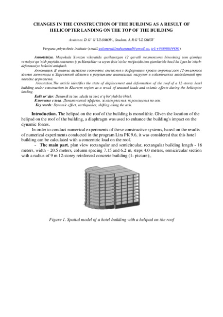
plan view rectangular and semicircular, rectangular building length - 16
meters, width - 20.5 meters, column spacing 7.15 and 6.2 m, steps 4.0 meters, semicircular section
with a radius of 9 m 12-storey reinforced concrete building (1- picture);,
Figure 1. Spatial model of a hotel building with a helipad on the roof

Figure 2. Schematic of the columns of a hotel building with a helipad on the roof.
Figure 3. A computational model of a building with a helicopter landing on the roof sections
In order to conduct numerical experiments of these constructive systems, Lira PK 9.6 was
modeled as a spatial reinforced concrete frame, and the following definitions and simplifications were
introduced in the process of transition from real to computational model:
Cutting surface of columns and beams of reinforced concrete frames - in the form of a square
circle, 600x600 mm; 500x500 mm; R = 275 mm.
The tag part of the helicopter landing on the roof of the building is monolithic and the cargo
is placed on a monolithic slab. Given the location of the helicopter landing on the roof of the building,
a diaphragm was used to enhance the building's impact on the dynamic forces.
The program does not model the foundation and its effect on the soil, and the study of this
effect is not included in this scientific work. Therefore, the models in the program are considered to
be firmly attached to a solid foundation, the effect of which is introduced by limiting displacements
and moments in all directions;
The height of each floor of the building is set at 3.5 meters.
The loads acting on the building structures were assumed to be the same for all building types
in order to conduct a numerical experiment. The normative and estimated value of cargo is calculated
in accordance with QMQ 2.01.07-96 - "Cargo and impacts" [3].
Загружение 7
Составляющая 1
М ассы собраны из загружений: 1,2,3,4,5
X
Y
Z

In buildings, the values of loads acting on the structure are the same. Since no girder plate
models have been created for the girder structures, the load-bearing girder is placed as a load
propagating force acting on the rod.
For this reason, from the amount of load acting on one square-meter part of the girder, the
load value affecting the length of one meter of the girder was calculated.
Loads are included in the program divided into several downloads, depending on the duration
of exposure. The values of loads and cargoes are as follows:
1 Load -
Specific weight of structures. In this case, the reliability coefficient on the load
γ
f
=1,1.
2 Load - the weight of the floor and floor used in buildings. In this case, according to
calculations, 0.27 t / m2 per square meter of arable land
Load 3 - The specific gravity of the helicopter is 12t.
Load 4 - Helicopter landing weight 24 t.
5 Loading - long-term loads Useful loads. QMQ 2.01.07-96 - According to Table 3 of
"Loads and Impacts", for a residential building is accepted a load of 0.24 t / m2 per square
meter of floor space, taking into account the reliability coefficient of load .
6 Loading - Human weight 0.24 t / m2
7 Loading - Snow load. According to QMQ 2.01.07-96 - "Loads and Impacts", for
Khorezm region - 0.05 t / m2, taking into account the coefficient of reliability of the load, 0.07 t
/ m2 is accepted.
8 Load - Seismic force acting on the X-axis.
9 Load - Seismic force acting on the Y-axis.
1 The formation of seismic loads and the introduction of seismic zone parameters is carried
out in three stages [4].
Phase 1. Formation of dynamic loads from static loads. At this stage, as mentioned above, the
value of seismic force is calculated by the weight of buildings and structures and the values of static
loads on them. In this case, using the dialog box "Formation of dynamic loads from static" of the
program, depending on the duration of exposure to each static load, enter the appropriate coefficient.
The value of the coefficient is given in Table 1 of QMQ 2.01.03-19 "Construction in seismic zones":
1-table
Types of loads
Accumulation coefficient
Constant
0.9
Long-term temporary
0.8
Short-term (covering and roofing)
0.5
Phase 2. Loading of seismic parameters of the area against seismic movements. In this case, the
area parameters are entered for the program to play "Tablets of dynamic loads".
From this point of view, the buildings located in their places are selected in the document -
QMQ 2.01.03-19 "Construction in seismic zones", and the following parameters are used in
accordance with the documentation and tables given in the document.
- Category and coefficient of responsibility of buildings from Table 2.3;
- Coefficient for determining the frequency of earthquakes from Table 2.4;
- coefficient depending on the number of floors of the building from Table 2.10;
- Table 2.12, maintaining the continuity of the structural system in accordance with paragraph
2.25;
- Coefficient taking into account the seismicity of the construction site from Table 2.7;
- vibration decrement from Table 2.9;
- address index from Table 2.2;
The grunt category is selected from Table 1 [2].

Step 3. Loading of the boundary inelastic deformation for carcass elements. In this case, the
values are given using the gaming program of the same name of Lira PC 9.6. For carcass elements,
this value is taken from Table 2.5 of QMQ 2.01.03-96 “Construction in seismic zones”. The
abbreviation for this table is as follows:
2- table
№
Constructive solutions of buildings
Boundary inelastic
deformation (μ
k
)
1
Frame systems
-reinforced concrete
-stool
10,0
15,0
2
Frame-bonding systems
-reinforced concrete
-stool
7,5
10,0
By performing the above steps, the seismic zone effect can be modeled in the program.
For each type of reinforced concrete structures under consideration, the appropriate values
should be entered separately based on the tables above. Once the appropriate values have been
entered, the final step for the numerical analysis is to perform the step of compiling the set of
calculated voltages.
The set of calculated voltages is formed using the dialog box "Table RSU" of the program. In
this case, a table is formed based on the types of downloads, separated by the duration of exposure.
The program considers all cases of interaction of different loads on the basis of the entered data,
identifies the most unfavorable set and automatically performs subsequent calculations on the basis
of this set [4].
Figure 4. Window to form a set of calculated stresses.
Once this set is formed, the program can automatically perform calculations. To do this,
launch the command "Mode", "Run raschet".
Based on the above calculation procedure, numerical analyzes were performed at all research
sites. The results can be printed in tabular or graphical form using the "Mode", "Results of the
calculation" command. By analyzing the published results, appropriate conclusions can be drawn.
The Lira PC 9.6 software has sufficient capabilities to compare the results of a number of
experiments conducted from different perspectives. Basic information about the results of the
calculation can be found in the "Protocol of the solution" function of the "Standard Tables" window
of the program.
We consider the displacements caused by seismic forces in reinforced concrete structures
using the graphical printing function of the results of the program Lira PK 9.6 [4].

Figure 5. Movements along the X-axis of a building where there is no helicopter landing area on
the roof sections.
Figure 6. Movements along the U-axis of a building that does not have a helicopter landing area on
the roof.

Figure 7 Movements along the X-axis of a building with a helicopter landing area in the roof sections.
Figure 8. Movements along the Y-axis of a building with a helicopter landing area on the
roof.
Summarizing the above results can be expressed in the following table:
3-table
№
The name of the elements
Maximum
displacement in
the X-axis
direction, mm
Maximum
displacement in
the Y-axis
direction, mm
1
A building with no helicopter
landing area on the roof
99
108
2
A building with a helicopter
landing area on the roof
102
110

The reinforcement cutting surfaces and reinforcement percentages in the columns of the
carcasses considered in the Conli experiments are carried out using the Lira ARM module program
designed to calculate the reinforcement cutting surfaces of the Lira PK 9.6 program. The percentage
of reinforcement in the elements of reinforced concrete frames is given in the following figures..
Figure 9. Percentage of reinforcement in the columns of a building that does not have a helicopter
landing area on the roof.
Figure 10. Percentage of reinforcement in the beams of a building that does not have a helicopter
landing area on the roof.
Figure 11. Percentage of reinforcement in the columns of the building with a helicopter landing
area on the roof.
X
Y
Z
%
0.0599
0.21
0.36
0.509
0.659
0.809
0.959
1.11
1.26
Процент армирования Несимметричное армирование . Максимум 1.26 в элементе 8470.
X
Y
Z
%
0.349
0.618
0.888
1.16
1.43
1.7
1.96
2.23
2.51
Процент армирования Симметричное армирование . Максимум 2.50 в элементе 6304.
X
Y
Z
%
0.349
0.571
0.793
1.01
1.24
1.46
1.68
1.9
2.12
Процент армирования Симметричное армирование . Максимум 2.12 в элементе 6304.

Figure 12. Percentage of reinforcement in the beams of the building with a helicopter
landing area on the roof.
We summarize these results in the following table:
Table 4
№
The name of the elements
Percentage of maximum
reinforcement in columns and
beams,%
1
The roof of a building with no
helicopter landing area
2.12
2
Roof of a building with no
helicopter landing area on the
roof
1.26
3
The roof of the building with a
helicopter landing area
2.51
4
The roof of the building with a
helicopter landing area on the
roof
1.34
Information about the roof of the building where the helicopter will land on the roof.
Figure 15. Slab contraction joints should intersect at the openings for columns and should
intersect at the openings for columns.
X
Y
Z
%
0.0599
0.22
0.38
0.539
0.699
0.859
1.02
1.18
1.34
Процент армирования Несимметричное армирование . Максимум 1.34 в элементе 8470.
Загружение 3 нег вер статик
Изополя перемещений по Z(G)
Единицы измерения - мм
-1.81
-1.51
-1.51
-1.21
-1.21
-0.907
-0.907
-0.604
-0.604
-0.302
-0.302
-0.00145
-0.00145
0.00145
0.00145
0.145
X
Y
Z

Figure 16. Reinforcement of the slab formed by the simultaneous action of seismic loads during the
helicopter landing on the roof slab.
Figure 17. Reinforcement of the roof slab under the influence of seismic loads on the
building.
Table 5
№
The name of the elements
Maximum
reinforcement used
for slabs, Sm2 / m2
Slab contraction joints
%
1
A building with no helicopter
landing area on the roof
3.93
51.1
2
A building with a helicopter
landing area on the roof
7.69
100
3
Slab contraction joints,%
2.76
48.9
CONCLUSION
1.Based on the results of a number of experiments conducted in the program Lira PK 9.6, it
was found that this hotel building can be hibernated with a concentric load on the roof.
2. QMQ 2.01.07-96 - The normative document "Loads and Impacts" does not provide a
calculation of the concentric load that can be poured on the roof of the building, and it is
recommended to use this computing technology.
3. Based on the results of numerical experiments conducted in Lira PK 9.6 program with an
6089
6095
6102
6109
6117
6124
X
Y
cm2/m
0
s200d4
0.63
s200d5
0.98
s200d6
1.41
s200d8
2.52
s200d10
3.93
s200d12
5.66
s200d14
7.69
Площадь арматуры на 1пм по оси Y у нижней грани (балки-стенки - посередине); максимум в элементе 6109
6089
6095
6102
6109
6117
6124
X
Y
cm2/m
0
s200d4
0.63
s200d5
0.98
s200d6
1.41
s200d8
2.52
s200d10
3.93
Площадь арматуры на 1пм по оси Y у нижней грани (балки-стенки - посередине); максимум в элементе 6109

unusual load on the roof of the building, it was determined that the building is fully resistant to the
effects of dynamic forces.
4. In columns and beams of a building with a helicopter landing area on the roof, the percentage
of reinforcement in the columns and beams is higher than in a building without a helipad, as shown
in Tables 4 and 5.
LIST OF USED LITERATURE:
1.
QMQ. 2.03.01-1996. Concrete and reinforced concrete structures. O’z.R. DAQQ.T.: 1998.
2.
ҚМҚ. 2.01.03-19. Construction in seismic areas. Toshkent 2019.
3.
ҚМҚ 2.01.07-96 – “Loads and effects” O’z.R. DAQQ.T.: 1997
4.
ПРОГРАММНЫЙ КОМПЛЕКС ЛИРА-САПР®. User guide. Teaching examples Romashkina M.A., Titok V.P.
Under the editorship of Academician RAASN Gorodetsky A.S. Electronic edition, 2018.
5.
“High – rise buildings structures and materials” February 2018, Sarajevo, Bosnia and Herzegovina Authors: Ilda
Kovačević Sanin Džidić.
6.
“Structural design of high-rise buildings” Lund university 2016, Authors: Erik Hallebrand and Wilhelm Jakobsson.
7.
Ali M.M, Moon.K S, 2007, “Structural Developments in Tall Buildings: Current Trends and Future Prospects",
Invited Review Paper of Architectural Science Review, Volume 50.3, University of Sydney, AU, pp 205-223
8.
Craighead G, 2009. “High-Rise Building Definition, Development and Use”, Butterworth-Heinemann is an imprint
of Elsevier, 30 Corporate Drive, Suite 400, Burlington, MA 01803, USA, Linacre House, Jordan Hill, Oxford OX2.
9.
Anil K. Chopra, Third Edition (2011) of Dynamics of structure, in this book in chapter Response to Arbitrary, step
and pulse Excitation page no: 161.
10.
Gianluca Cusatis and Daniele Pelessone (2009), General paper on “The Mesolevel simulation of reinforced concrete
structures under impact loadings.” Rensselaer Polytechnic Institute, Troy (NY), USA.


