

Assessment of the Dynamics of Axisemitric Shell Structures
Considering Their Viscoelastic Properties
Shoolim Salimov
1*
, Tulkin Mavlanov
2
1
Tashkent University of Applied Sciences, Gavhar Str. 1, Tashkent 100149, Uzbekistan
2
NRU “TIIAME”,Tashkent, Kori Niyazi St.39, Uzbekistan.
https://doi.org/10.5281/zenodo.10471379
Keywords:
Shell element, shell structure, annular element, coordinate surface, potential strain energy, external load,
viscoelastic property, nodal element, design scheme.
Abstract:
The paper presents the statement and methods for solving dynamic problems of multiply connected
structurally inhomogeneous shell structures, which make it possible to reduce the problem of calculating a
wide class of engineering structures to computer-aided design tasks. On the basis of numerical experiments
and multi-parameter analysis of the system as a whole, a number of fundamentally important applied problems
have been solved for calculating the dynamic characteristics of oscillations (frequencies, modes, determinant
resonant amplitudes and damping coefficients) of special structures depending on the parameters of structural
inhomogeneity. The results obtained made it possible to identify some mechanical effects of theoretical and
practical importance. The developed methods and algorithms allow, at the stage of inhomogeneous systems
design, combining inhomogeneous materials and connections with various rheological properties, to establish
the ranges of parameter values for numerical-experimental search of the most rational (in terms of efficiency)
dissipative properties and material consumption of engineering structures. It was established that an account
for nonlinear strain in the material does not strongly distort the picture of linearly viscoelastic calculation.
1 INTRODUCTION
Theoretical and experimental foundations of
nonlinear rheological properties manifestation in
various elements of structurally inhomogeneous,
complex multiply connected shell structures are given
in fundamental publications [1-12]. Despite this, the
assessment of the stress-strain state of shell structures
considering inhomogeneous, viscoelastic properties
is carried out only within the framework of linear
viscoelasticity.
Recently, a number of works have been published
[13], which take into account the manifestation of
elastic, viscoelastic linear and nonlinear properties of
the material of shell structures under dynamic effects.
A summary of some of them is given below.
In [13], a calculation model of the foundation base
deformation was presented based on the layer-by-
layer summation method taking into account the
components of the deviator and the ball tensor, the
ratio between them being different at different points
of the foundation. Nonlinear volume strain of soil
over time was considered taking into account the
compaction of soil bearing layer.
Dynamic reaction of soil dams [13] was studied
with account for nonlinear and viscoelastic properties
of soil; the dependence of dynamic reactions on load
and mechanical properties of soil was established.
Based on the results of experiments, local laws of
interaction of extended underground pipelines and
fragments of the outer surface of underground
structures with soils of disturbed and undisturbed
structure were constructed [14].
In [15], using the nonlinear rheological models,
the stress state of the dam was investigated. The
possibility of using the model was demonstrated by
comparing the numerical results with the results of
laboratory tests.
In [16], the generalized rheological models of
unsaturated and water-saturated soils were proposed

and the corresponding equations were derived, used
in quantitative assessment of additional residual
strains and stresses in soil. A one-dimensional
problem of consolidating a layer of not completely
water-saturated soil under cyclic variation in external
load was solved.
A model and a set of determinant relations for a
rheological model of soft soils were proposed in [17].
The possibility of using this model was confirmed by
a number of rheological consolidation experiments
under different loading velocities.
In [18], a tendency was shown to increase the
instantaneous strain modulus with an increase in
creep. A nonlinear creep model has been introduced
for soft soils, in which the creep decay was described
by a nonlinear hardening function and viscosity
coefficient, and the nonlinear creep curves were in
good agreement with experimental data.
The behavior of specific structures using the
hereditary theory of viscoelasticity under dynamic
loading has not been sufficiently studied though
widely considered in literature sources [19, 20, 21,
22]. The overwhelming number of publications
related to dynamic problems of hereditary theory of
viscoelasticity was addressed to the calculation of
(linear and geometrically nonlinear) thin-walled
structures
—
beams, plates, and shells [12, 23].
The scheme for solving dynamic problems of
viscoelasticity for thin-walled structures is fairly
standard. Choosing a coordinate function that
satisfies the boundary conditions, the original
problem can be reduced to the problem of oscillations
of a system with finite number of degrees of freedom,
that is, to a system of linear or nonlinear integro-
differential equations with one independent time
variable [12, 23]. As a rule, trigonometric or beam
functions are used as coordinate functions. Such a
choice of coordinate functions limits the class of
problems to be solved to the structures of the simplest
configurations - beams of constant sections, a
rectangular plate, a cylindrical shell [12].
The authors of those publications, assuming a
number of inaccuracies in coordinate functions
selection, tried to increase the solution accuracy of the
system of integro-differential equations. However,
for structures with real geometry, it is impossible to
choose analytical coordinate functions that satisfy the
boundary conditions of the problem.
The above review of known works shows the need
to assess the stress-strain state and dynamic behavior
of structurally inhomogeneous shell designs of earth
structures considering not only rheological properties
of shell structures, but the heterogeneous structural
features and real geometry.
In this paper, we present the methods, algorithm,
and results of a study of dynamic behavior of multiply
connected
structurally
inhomogeneous
shell
structures, taking into account viscoelastic properties
of the material under various dynamic effects.
2 Materials and Methods
The purpose of this work is the solar radiation of
When choosing a computational model as a whole, it
is necessary to be able to evaluate the effect of one or
another structural element on its behavior under real
loading, since sometimes small changes in
computational model can have a significant impact on
the results of structural analysis. The most complete
design scheme for the vast majority of aircraft
structures, underground and aboveground structures,
structures in shipbuilding and other branches of
machine building leads to statically indefinable
systems. One of such systems is an arbitrary
axisymmetric design of shells of rotation and circular
frames. As an example, consider the designs scheme
shown in Fig. 1. In the general case, these are the
multi-connected shell structures representing an
arbitrary composition of multilayer shells of rotations
and circular frames, and an arbitrary composition of
multi-layer cylindrical shells of non-circular cross
section and rectilinear stringers.
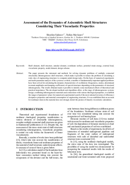
Figure. 1. Design scheme of shell structure
By analogy with [12], the structure (Fig. 1) is
presented as an arbitrary composition of nodes
interconnected by shell elements. Nodal elements in
this case are: end and intermediate frames (nodes 3,
5, and 6), free and supported ends of the shells (node
6), the parallels of direct connection of links or lines
along which geometrical and mechanical parameters
or components of applied loads are broken (nodes 2
and 4), construction poles in which the shell
generatrix intersect with the axis of rotation (node 1).
Shell elements are the shells of revolution connecting
nodal elements. Elements of “link” type realize the
connection between the nodal structural elements or
between the nodal elements and the fixed support and
are the spring elements with some real rigidity
characteristics.
Shell elements are the cylindrical shells connecting
the nodal elements. Each shell element of the

considered classes of structures can be isotropic,
orthotropic, or structurally orthotropic (Fig. 2) and
possess
elastic
viscoelastic
properties
with
significantly different hereditary functions of the
material in the element structure.
Shell elements in the first-class structures can have
variable rigidity and mechanical characteristics of the
generatrix, and shell elements in the second-class
structures are the variables along the guide. For each
shell element the Kirchhoff-Love hypotheses must be
fair. No restrictions are imposed on the geometry of
the generatrix of the shells of revolution and on the
geometry of the guides of the cylindrical shells.
Figure 2. Structure element
Each circular frame and each stringer can possess
elastic or viscoelastic properties with significantly
different theological characteristics. Cross sections of
frames and stringers are considered non-deformable,
i.e. the frames are considered according to the
classical scheme of a circular ring, and the stringers -
according to the classical scheme of a straight rod.
The rigidity characteristics of links can be either
elastic or viscoelastic ones, described by the
hereditary Boltzmann-Volterra relationships. It is
assumed that a system of external dynamic loads acts
on the structure.
In the particular case when there are no external
mechanical influences, free damped vibrations of the
structure are considered, in the presence of periodic
influences - the steady-state forced vibrations.
Assume that the connection between nodes
𝑖
and
𝑗
is
realized by
𝑀
𝑖𝑗
viscoelastic hereditary links, the triple
index
𝑖𝑗𝑠(1 ≤ 𝑆 ≤ 𝑀
𝑖𝑗
)
is assigned to each link and
all quantities related to it. The structure has
𝑁
е
=
∑
∑
М
𝑖𝑗
𝑁
2
𝑗=𝑖+1
𝑁
𝑟−1
𝑖=1
viscoelastic bonds. To denote the
values related to the shell element or viscoelastic link,
we will use, where this does not cause any
misunderstanding, the order number
𝑝(1 ≤
р
≤
𝑁
𝑠
)
of the element or the order number
𝑝(1 ≤
р
≤
𝑁
𝑒
)
of the link.
By analogy with [12], for each shell element, we
introduce a local coordinate system 0 α
1
α
2
r. For this,
a surface is defined inside the shell element, called the
coordinate surface. The position of the points on this
surface is determined by the Gaussian curvilinear
coordinates α
1
andα
2
directed along the lines of
principal curvature. In this case, α
1
is directed along
the guide, and α
2
is directed along the generatrix of
cylindrical element. The
𝑧
coordinate, which
determines the distance from a certain point of the
shell element to the coordinate surface is directed so
that the coordinate system
Oα
1
α
2
z
forms right-hand
orthogonal coordinate system.
Next, consider a thin-walled axisymmetric shell
structure. Link the global right-hand rectangular
coordinate system
Ox
1
x
2
y
with this structure (Fig.3).
The
𝑥
1
axis is directed along the structure axis of
rotation. The structure is presented as an arbitrary
composition of
𝑁
𝑟
annular nodal elements,
𝑁
𝑠
shells
of revolution, and
𝑁
𝑒
viscoelastic links (Fig.4).
The numbering of nodes, shell elements and links, as
well as the indexation of all quantities related to
nodes, shell elements and links, is carried out by
analogy with prismatic structures. It is known that the
internal geometry of the coordinate surface can be
characterized by the first quadratic form.
Figure 3. Design scheme of shell structure
Figure 4. Nodal and shell elements
If the coordinates α
1
andα
2
correspond to the lines of
principal curvature, then the differentials of the
coordinate lines arcs can be expressed in terms of the
differentials of curvilinear coordinates
𝑑𝑆
1
= 𝐴
1
𝑑𝛼
1
, 𝑑𝑆
2
= 𝐴
2
𝑑𝛼
2
,
(1)
where
А
1
and
А
2
are the Lame coefficients. The
external surface geometry in the selected coordinate
system is characterized by the main radii of curvature
R
1
and
R
2
(or by the main curvatures
Н
1
=
1
𝑅
1
and
Н
2
=
1
𝑅
2
).
The quantities
𝐴
1
(𝛼
1
, 𝑎
2
)
,
𝐴
2
(𝛼
1
, 𝑎
2
)
,
𝐻
1
(𝛼
1
, 𝑎
2
)
,
𝐻
2
(𝛼
1
, 𝑎
2
)
must satisfy the Gauss-Codazzi relations
known from the theory of surfaces
𝜕
𝜕𝛼
(К
2
А
2
) = К
1
𝜕А
2
𝜕А
3
(1 ⇄ 𝑧),

𝜕
𝜕𝛼
(
1
𝐴
1
∙
𝜕𝐴
2
𝜕𝛼
1
) +
𝜕
𝜕𝛼2
(
1
𝐴
2
∙
𝜕𝐴
1
𝜕𝛼
2
) = −𝐾
1
𝐾
2
𝐴
1
𝐴
2
(2)
In the case of axisymmetric shells, the quantities
𝐴
1
, 𝐴
2
, 𝐾
1
, 𝐾
2
do not depend on coordinate
𝛼
2
and
depend only on coordinate
𝛼
1
directed along the
generatrix. Gauss-Codazzi relations are simplified
1
𝐴
1
∙
𝜕
𝜕𝛼
1
= (𝐾
1
− 𝐾
2
)
1
𝐴
1
𝐴
2
∙
𝜕𝐴
2
𝜕𝛼
2
,
1
𝐴
1
∙
𝜕
𝜕𝛼1
= (
1
𝐴
1
∙
𝜕𝐴
2
𝜕𝛼
1
) = −𝐾
1
𝐾
2
𝐴
2
.
(3)
Let us determine the position of points on the
coordinate surface of the considered shell element by
the Gaussian curvilinear coordinates
𝛼
1
𝑎𝑛𝑑 𝑎
2
;
their positive directions are shown in Fig.5. Introduce
the following notation [12]
(… )
′
=
1
𝐴
1
∙
𝜕(… )
𝜕𝑎
1
, (… )
∙
=
1
𝐴
2
∙
𝜕(… )
𝜕𝑎
2
, 𝜓 =
1
𝐴
2
∙
(4)
The rotations of the normal to coordinate surface of
the shell element can be expressed in terms of the
displacements of the points of coordinate surface
𝑢, 𝑣, 𝑎𝑛𝑑 𝜔
by formulas
𝛩
1
= −𝜔
′
+ 𝐾
1
𝑢, 𝛩
2
= −𝜔
∙
+ 𝐾
2
𝑣
(5)
The extensions and the shift of coordinate surface are
related to the displacements
𝑢, 𝑣, 𝑎𝑛𝑑 𝜔
by relations
Е
11
= 𝑢′ + 𝐾
1
𝜔,
Е
22
= 𝑣
∙
+ 𝜓𝑢 + 𝐾
2
𝜔,
Е
12
= 𝐸
21
+ 𝑣′ − 𝜓𝑣 + 𝑢
.
(6)
The components of the bending strain of coordinate
surface (changes in curvature and torsion) are related
to the displacements
𝑢, 𝑣, 𝜔
and rotations
Ө
1
and
Ө
2
by relationships
К
11
= 𝛩
1
′
,
К
22
= 𝛩
2
∙
+ 𝜓𝛩
1
,
К
12
= 𝛩
1
.
− 𝜓𝛩
2
+ К
2
𝑣
′
,
К
21
= 𝛩
2
′
+ К
1
(𝑢
.
− 𝜓𝑣).
(7)
By direct substitution of relationships (5) into the
torsion expressions of coordinate surface
К
12
and
К
21
using the Gauss-Codazzi relations (3), it is easy
to see that
К
12
= К
21
.
The components of strain at
a point of the shell element that is at a distance z from
the coordinate surface are related to the components
of tangential and bending strain of this surface by
relations
𝜀
11
= Е
11
+ 𝑍 ∙ 𝐾
11
(1 ⇄ 2),
𝜀
12
= Е
12
+ 2𝑍 ∙ 𝐾
12
(8)
Consider a circular ring, the cross section of which is
assumed to be small in comparison with the distance
𝐿
from the axis of rotation to the line of centers of
gravity (the midline), as a design scheme of the
annular element of axisymmetric shell structure. It is
assumed that the plane of the cross section is strain-
free [12]
The position of the ring point is determined by the
coordinates
х, 𝛼
2
and 𝑧
The displacements of the
point located on the ring midline in directions х,
𝛼
2
and
𝑧
are denoted by
𝑢, 𝑣, 𝜔
respectively, and the
rotation of ring cross section relative to this line -
by
𝜑
. Rotations of the ring cross section relative to
the
𝑧
and
𝑥
axes resulting from the ring strain are
expressed through the displacements of the ring
midline according to formulas
𝜑
х
= −𝑢
∙
, 𝜑
𝑧
= −𝜔
.
+ 𝐾
𝑟
𝑣
(9)
where
(… ) =
1
𝑟
𝑑(… )
𝑑𝛼
2
, 𝐾
𝑟
=
1
𝑟
(10)
The extension of the ring midline is expressed
through the displacements of this line by formula
𝜀 = 𝑣
∙
+ 𝐾
𝑟
𝜔
(11)
Changes in curvature and torsion of the ring midline
and the rotation of the ring cross section relative to
the axis
𝛼
2
can be expressed through the
displacements of this line by formulas
𝑥
𝑥
= −𝑢
..
− 𝐾
𝑟
𝜑, 𝑥
𝑧
= −𝜔
..
− 𝐾
𝑟
𝑣
.
,
𝑥 = −𝜑
.
− 𝐾
𝑟
𝑢
.
(12)
The strains of the ring point with the coordinates
𝑥,
𝛼
2
and
z
are determined by formula
𝜀(𝑥, 𝛼
2
, 𝑧) = 𝜀 + 𝑥 ∙ 𝑥
𝑥
+ 𝑧 ∙ 𝑥
𝑧
(13)
As a design scheme of connections between nodal
elements, consider the links of spring types [12]. The
displacements of the origin of connections
indirections
𝑥, 𝛼
2
and
𝑧
, we denote by
u
н
, v
н
,
𝜔
н
the
rotation relative to the axes
𝛼
2
by
𝜃
н
. Similar
quantities for the end of the connection are denoted
by
𝑢
к
,
𝑣
к
,
𝜔
к
, 𝜃
к
. Then changes in connections lengths
in the directions
x
,
𝛼
2
and
z
are calculated by formulas
∆𝑢 = 𝑢
к
− 𝑢
н
, ∆𝑣 = 𝑣
к
− 𝑣
н
,
∆𝜔 = 𝜔
к
− 𝜔
н
,
(14)
and the change in the angle of rotation - according to
formula
𝛥𝛩 = 𝛩
к
− 𝛩
н
(15)
The conditions of continuity of displacements
between shell and nodal elements, links and nodal
elements are not presented here, because from [12] it
is possible and easy to extend all the obtained
relations to structurally inhomogeneous shell
structures.
Establish just the relationship between vector
𝑉
𝑖
= [𝑢
н
𝜔
н
𝛩
н
𝜐
н
]
𝑇
(16)
generalized displacements
𝑖𝑗𝑠
of a spring-type
element adjacent to the
𝑖
-th annular element and the
vector
𝛥
𝑖
of generalized displacements of this annular
element.
3
RESULTS AND DISCUSSIONS
Let each shell element of the considered structure be
affected by loads
𝑞
1
𝑃
𝑞
2
𝑃
𝑞
3
𝑃
distributed over the
coordinate surface. Assume that for each annular
element of the structure the external loads reduced to
the midline of this element are applied.

To obtain the equilibrium equations of the structure,
the variational Lagrange equation is used:
∑ 𝛿
Э
р
+
𝑁
𝑠
р
=1
∑ 𝛿
Э
𝑖
+
𝑁
𝑟
𝑖=1
∑ 𝛿
Э
𝑒
− ∑ 𝛿𝐴
𝑝
− ∑ 𝛿𝐴
𝑖
= 0
𝑁
𝑟
𝑖=1
𝑁
𝑠
𝑝=1
𝑁
𝑒
𝑙=1
(17)
Where
𝛿
Э
р
is the variation of the potential strain
energy of the
𝑝
-th shell element;
𝛿
Э
𝑖
is the variation
of the potential strain energy of the
𝑖
-th annular
element;
𝛿
Э
𝑒
is the variation of the potential strain
energy of the
𝑒
-th viscoelastic link;
𝛿
А
Р
is the
elementary work of external loads applied to the
𝑝
-th
shell element;
𝛿
А
𝑖
is the elementary work of external
loads applied to the
𝑖
-th annular element.
Introduce the displacement vector
𝑈
р
⃗⃗⃗⃗ = [𝑢
𝑃
, 𝑣
𝑃
, 𝑤
𝑃
]
,
the component of which is the displacements of the
points of coordinate surface of the
𝑝
-th shell element
in directions
𝛼
1
,
𝛼
2
, and
𝑧
respectively, the vector
𝑈
𝑖
⃗⃗⃗ = [𝑢
𝑖
𝜔
𝑖
𝜑
𝑖
𝑣
𝑖
𝜑
𝑥𝑖
𝜑
𝑧𝑖
]
𝑇
of
generalized
displacements of the midline of annular element and
vectors
𝑉
не
= [𝑢
не
𝑤
не
𝛩
не
𝑣
не
]
𝑇
,
𝑉
ке
= [𝑢
ке
𝑤
ке
𝛩
ке
𝑣
ке
]
𝑇
(18)
generalized displacements at the beginning and end
of a viscoelastic link are with order number e.
Then the elementary work of external loads applied
to the
𝑝
-th shell element can be written in the form
𝛿
А
р
= ∫
𝜙(𝑞
𝑃
, 𝛿𝑈
𝑝
)𝐴
1
𝑃
𝛼
1𝑒
𝑝
𝛼
10
𝑝
𝐴
2
𝑃
𝑑𝛼
1
𝑃
𝑑𝛼
2
𝑃
(19)
and the elementary work of external loads applied to
the
𝑖
-th annular element in the form
𝛿А
𝑖
= 𝜙(𝑓
𝑖
, 𝛿𝑈
𝑖
)𝑟
𝑖
𝑑𝛼
2
.
The variation of the potential strain energy of the
𝑝
-
th shell element can be represented as
𝛿Э
р
= ∫
𝜙(𝑁
𝑃
, 𝛿𝜀
𝑝
)𝐴
1
𝑃
𝛼
1𝑒
𝑝
𝛼
10
𝑝
𝐴
2
𝑃
𝑑𝛼
1
𝑃
𝑑𝛼
2
𝑃
(20)
The variation of the potential strain energy of the
𝑖
-th
annular element is presented in the form
𝛿Э
𝑖
= 𝜙(𝑄
𝑘𝑖
, 𝛿𝜀
𝑖
)𝑟
𝑖
𝑑𝛼
2
Variation of the potential strain energy of the
𝑒
-th
viscoelastic link can be represented in the form
𝛿Э
е
= 𝜙[(𝑁
се
, 𝛿𝑉
ке
) − (𝑁
𝑐𝑒
, 𝛿𝑉
не
)]𝑟
𝑒
,d
𝛼
2
(21)
The expression for
𝛿А
𝑖
is given in the form
𝛿А
𝑖
= 𝜙 (||𝜃
𝑖
̅ || 𝑓
𝑖
,
, 𝛿
Δ
𝑖
) 𝑟
𝑖
𝑑𝛼
2
,
|𝛩
𝑖
̅ | = |
1 0
0 0
(… )
0
0 1
0 0
0
(… )
0 0
1 0
0
0
0 0
0 1
0
𝐾
𝑟𝑖
|
(22)
Using the Green's formulas and equality
∫
𝐹
1
𝜕𝐹
2
𝜕𝛼
1
𝑑𝑎
1
= 𝐹
1
𝐹
2
∫
− ∫
𝜕𝐹
1
𝜕𝛼
1
𝐹
2
𝑑𝛼
1
𝛼
1𝑒
𝛼
10
𝛼
1𝑒
𝛼
10
,
expression for
𝛿Э
𝑟
is given in the form
𝛿Э
р
= 𝜙 ∫
𝜙(𝐿
𝑝
, 𝛿𝑈
𝑝
)
𝛼
1𝑒
𝑝
𝛼
10
𝑝
𝐴
1
𝑝
𝐴
2
𝑝
𝑑𝛼
1
𝑝
𝑑𝛼
2
𝑝
+ 𝜙 (
𝑄
𝑝
𝛼
1𝑒
𝑝
,
𝛿𝑊
𝑝
𝛼
1𝑒
𝑝
) 𝐴
2
(𝛼
1𝑒
𝑝
)𝑑𝛼
2
−
−𝜙 (
𝑄
𝑝
𝛼
10
𝑝
,
𝛿𝑊
𝑝
𝛼
10
𝑝
) 𝐴
2
(𝛼
10
𝑝
)𝑑𝛼
2
(23)
here
𝑄
𝑝
=
{
𝑇
11𝑝
𝑄
11𝑝
+ 𝐻
𝑝
∙
𝑀
11𝑝
𝑆
𝑝
+ 2𝐾
2𝑝
∙ 𝐻
𝑝
}
, 𝑊
𝑝
= {
𝑢
𝑝
𝑤
𝑝
𝛩
1𝑝
𝑣
𝑝
}
is the vector of generalized forces and the vector of
generalized displacements of the boundary contours
of shell element, respectively, adjacent to the
corresponding annular elements of the structure. The
positive directions of these forces and displacements
coincide with the positive directions of the
corresponding internal forces and displacements in
the shell element. The components of the vector
𝐿
𝑝
in expression for
𝛿Э
р
have the following form (for
the simplicity index
𝑝
is omitted)
𝐿
1
= 𝑇
11
′
+ 𝜓(𝑇
11
− 𝑇
22
) + 𝑆
∙
+ 𝐾
1
(𝑄
11
+ 𝐻
∙
),
𝐿
2
= 𝑆
′
+ 2𝜓(𝑆 + 𝐾
1
𝐻) + 𝑇
22
∙
+ 𝐾
2
(𝑄
22
+ 𝐻
′
),
(24)
𝐿
3
= 𝑄
11
′
+ 𝜓𝑄
11
+ 𝑄
22
∙
− 𝐾
1
𝑇
11
− 𝐾
2
𝑇
22,
where
𝑄
11
= 𝑀
11
′
+ 𝜓(𝑀
11
− 𝑀
22
) + 𝐻
∙
,
𝑄
22
= 𝐻
′
+ 2𝜓𝐻 + 𝑀
22
∙
Using the Green's formula, the expression for
𝛿Э
𝑖
is
presented in the form
𝛿Э
𝑖
= −𝜙(𝐿
𝑟
𝑖
, 𝛿
Δ
𝑖
)𝑟
𝑖
𝑑𝛼
2
,
where (for the simplicity index
𝑖
is omitted)
𝐿
𝑟1
= 𝑀
𝑥
∙∙
− 𝐾
𝑟
𝑀
∙
,
𝐿
𝑟2
= 𝑀
𝑧
∙∙
− 𝐾
𝑟
𝑇
.
,
𝐿
𝑟3
= 𝑀
∙
+ 𝐾
𝑟
𝑀
𝑥
, (25)
𝐿
𝑟4
= 𝑇
∙
+ 𝐾
𝑟
𝑀
𝑧
Substituting the obtained expressions into the
variational Lagrange equation (24) we obtain:
− ∑ ∫
𝜙[(𝐿
𝑝
, 𝛿𝑈
𝑝
) + (𝑞
𝑝
, 𝛿𝑈
𝑝
)]𝐴
1
𝑝
𝛼
1𝑒
𝑝
𝛼
10
𝑝
𝑁
𝑠
𝑝=1
𝐴
2
𝑝
𝑑𝛼
1
𝑝
𝑑𝛼
2
𝑝
− ∑ 𝜙 (
𝑄
𝑝
𝛼
1𝑒
𝑝
,
𝛿𝑊
𝛼
1𝑒
𝑝
)
𝑁
𝑠
𝑝=1
𝐴
2
(𝛼
1𝑒
𝑝
)𝐴
2
𝑝
𝑑𝑎
2
−
− ∑ 𝜙 (
𝑄
𝑝
𝛼
10
𝑝
,
𝛿𝑊
𝛼
10
𝑝
)
𝑁
𝑠
𝑝=1
𝐴
2
(𝛼
10
𝑝
)𝑑𝑎
2
−
− ∑ 𝜙[(𝐿
𝑟
𝑖
, 𝛿
Δ
𝑖
) + (‖𝛩
𝑖
‖𝑓
𝑖
, 𝛿
Δ
𝑖
)]𝑟
𝑖
𝑑𝛼
2
+
𝑁
𝑟
𝑖=1
+ ∑ 𝜙[(𝑁
𝑐𝑒
, 𝛿𝑉
ке
) − (𝑁
𝑐𝑒
, 𝛿𝑉
не
)]𝑟
𝑒
𝑑𝛼
2
=
𝑁
𝑟
р=1
= 0 (26)

In the second and third terms of relationship (26), the
summation over p is replaced by summation over
𝑖
,
the index
𝑝
by the indices
𝑖 𝑗 𝑠
. For the
𝑖 𝑗 𝑠
-th shell
element adjacent to the
𝑖
-th annular element, we
calculate the integral
𝐽 = 𝜙(𝑄
𝑖
𝑖𝑗𝑠
, 𝛿𝑊
𝑖
𝑖𝑗𝑠
)𝐴
2
(𝛼
1𝑖
𝑖𝑗𝑠
)𝑑𝛼
2
(27)
It is obvious that
𝐴
2
(𝛼
1𝑖
𝑖𝑗𝑠
) = 𝑟
𝑖
(1 +
𝑍
𝑖
𝑖𝑗𝑠
𝑟
𝑖
)
,
where
𝑧
𝑖
𝑖𝑗𝑠
- is the coordinate of the contact point of
𝑖𝑗𝑠
-th shell element adjacent to the
𝑖
-th annular
element, related to the vector of generalized
displacements Δ
𝑖
of this annular element by relation
𝑊
𝑖
𝑖𝑗𝑠
= [𝜑̅
𝑖
𝑖𝑗𝑠
]
𝑇
Δ
𝑖
.
Substituting the relationships for
𝐴
2
(𝛼
1𝑖
𝑖𝑗𝑠
)
and
𝑊
𝑖
𝑖𝑗𝑠
into expression (27) we obtain:
𝐽 = (1 +
𝑍
𝑖
𝑖𝑗𝑠
𝑟
𝑖
) 𝜙(𝑄
𝑖
𝑖𝑗𝑠
, [𝜑̅
𝑖
𝑖𝑗𝑠
]𝛿
Δ
𝑖
)𝑟
𝑖
𝑑𝛼
2
(28)
It is easy to see that
𝜙 (𝑄
𝑖
𝑖𝑗𝑠
, [𝜑̅
𝑖
𝑖𝑗𝑠
]
𝑇
δ
Δ
𝑖
) 𝑟
𝑖
𝑑𝛼
2
=
= 𝜙([𝜂
𝑖
𝑖𝑗𝑠
]𝑄
𝑖
𝑖𝑗𝑠
, 𝛿
Δ
𝑖
)𝑟
𝑖
𝑑𝛼
2
(29)
[𝜂̅
𝑖
𝑖𝑗𝑠
] =
[
sin 𝛾
𝑖
cos 𝛾
𝑖
0
𝑥
𝑖
(… )
cos 𝛾
𝑖
sin 𝛾
𝑖
0
𝑧
𝑖
(… )
(𝑥
𝑖
sin 𝛾
𝑖
− 𝑥
𝑖
cos 𝛾
𝑖
)
(−𝑧
𝑖
cos 𝛾
𝑖
− 𝑥
𝑖
sin 𝛾
𝑖
)
1
0
0
0
0 1 + 𝐾
𝑟𝑖
𝑧
𝑖
]
(30)
In deriving equality (30), the Green formula was
used. In the fifth term of expression (26), the
summation over pis replaced by summing over
𝑖
, and
the index
𝑝
by the indices
𝑖𝑗𝑠
- th viscoelastic link, by
analogy with shell elements
𝜙(𝑁
𝑐
𝑖𝑗𝑠
, 𝛿𝑉
𝑖
𝑖𝑗𝑠
)𝑟
𝑐𝑖
𝑑𝑎
2
= 𝜙([𝜂̅
𝑖
𝑖𝑗𝑠
]𝑁
𝑐
𝑖𝑗𝑠
, 𝛿
Δ
𝑖
) (1 +
𝑧
𝑐𝑖
𝑖𝑗𝑠
𝑟
𝑖
) 𝑟
𝑖
𝑑𝛼
2
(31)
where the matrix
[𝜂̅
с𝑖
𝑖𝑗𝑠
] = [𝜂̅
с𝑖
𝑖𝑗𝑠
]
at
𝛾 =
𝜋
2
Introducing to the second and fifth terms of
expression (17) the integrals over the middle surface
of the annular elements, we obtain the variational
Lagrange equation with complex coefficients in the
form:
− ∑ ∫
𝜙[(𝐿
𝑝
, 𝛿𝑈
𝑝
) + (𝑞
𝑝
, 𝛿𝑈
𝑝
)]𝐴
1
𝑝
𝛼
1𝑒
𝑝
𝛼
10
𝑝
𝑁
𝑠
𝑝=1
𝐴
2
𝑝
𝑑𝛼
1
𝑝
𝑑𝛼
2
−
− ∑ {𝜙[(𝐿
𝑟
𝑖
, 𝛿
Δ
𝑖
) + (‖𝛩̅
𝑖
‖𝑓
𝑖
, 𝛿
Δ
𝑖
)]
𝑁
𝑟
𝑖=1
+ ∑ ∑(𝜉
𝑐𝑖
𝑖𝑗𝑠
[𝜂̅
𝑖
𝑖𝑗𝑠
]𝑄
𝑖
𝑖𝑗𝑠
, 𝛿
Δ
𝑖
)
𝑠
𝑗
+ ∑ ∑(𝜉
𝑖𝑐
𝑖𝑗𝑠
[𝜂̅
𝑐𝑖
𝑖𝑗𝑠
]𝑁
𝑐𝑖
𝑖𝑗𝑠
, 𝛿
Δ
𝑖
)
𝑠
𝑗
𝑟
𝑖
𝑑𝛼
2
} (32)
where
𝜉
𝑖
𝑖𝑗𝑠
=
(1 + 𝐾
𝑟𝑖
𝑧
𝑖
𝑖𝑗𝑠
)𝑠𝑖𝑔𝑛[(𝑗 − 𝑖)(𝛼
1𝑒
𝑖𝑗𝑠
− 𝛼
10
𝑖𝑗𝑠
)],
𝜉
𝑐𝑖
𝑖𝑗𝑠
=
(1 + 𝐾
𝑟𝑖
𝑍
𝑐𝑖
𝑖𝑗𝑠
)𝑠𝑖𝑔𝑛(𝑗 − 𝑖)
At independent variations of
𝛿𝑈
𝑝
in the surface
coordinate of the
𝑝
-th shell element and independent
variations of
𝛿
Δ
𝑖
in the midline of the
𝑖
-th annular
element, from the variational Lagrange equation with
complex coefficients a system of interconnected
equilibrium equations of structurally inhomogeneous
shell structures is obtained
𝐿
𝑝
+ 𝑞
𝑝
= 0 (𝑝 = 1,2, … , 𝑁
𝑠
),
𝐿
𝑟
𝑖
+ ‖𝛩
𝑖
‖ ∙ 𝑓
𝑖
+ ∑ ∑ 𝜉
𝑐𝑖
𝑖𝑗𝑠
[𝜂̅
𝑖
𝑖𝑗𝑠
]𝑄
𝑖
𝑖𝑗𝑠
𝑠
𝑗
+ ∑ ∑ 𝜉
𝑐𝑖
𝑖𝑗𝑠
[𝜂̅
𝑐𝑖
𝑖𝑗𝑠
]𝑁
𝑐𝑖
𝑖𝑗𝑠
𝑠
𝑗
= 0, (𝑖 = 1,2, … , 𝑁
𝑟
) (33)
as well as the conditions of continuity of
displacements and relations of linear strains of
multiply connected structurally inhomogeneous
axisymmetric shell structures. Summation in
equations (33) is conducted over all shell elements
adjacent to the
𝑖
-th annular element.
The equations of motion for an arbitrary change in
external loads over timeare obtained from the
equations of statics (33) using the d'Alembert
principle. As a result, the following system of coupled
equations of motion of a multiply connected
structurally inhomogeneous shell structureis obtained
in a complex form:
𝐿
𝑝
+ 𝑞
𝑝
= (𝜏) − [𝜌̅
𝑝
]
𝜕
2
𝑈
𝑝
𝜕𝜏
2
= 0 (𝑝 = 0, … 𝑁
𝑠
)
(34)
𝐿
𝑟
𝑖
+ ‖𝛩̅
𝑖
‖𝑓
𝑖
(𝜏) − [𝐺
𝜔
]
𝜕
2
∆
𝑖
𝜕𝜏
2
= ∑ ∑ 𝜉
𝑐𝑖
𝑖𝑗𝑠
[𝜂̅
𝑖
𝑖𝑗𝑠
]𝑄
𝑖
𝑖𝑗𝑠
𝑠
𝑗
+ ∑ ∑ 𝜉
𝑐𝑖
𝑖𝑗𝑠
[𝜂̅
𝑐𝑖
𝑖𝑗𝑠
]𝑁
𝑐𝑖
𝑖𝑗𝑠
= 0
𝑠
𝑗
,
(𝑖 = 1, … 𝑁
𝑟
)(35)
[𝐺
𝜔
] = 𝜌
𝑖
𝐹
𝑖
[
1
0 0 0
0
1 0 0
0
0 1 0
0
0 0 1
], [𝜌̅
р
]
= 𝜌̅
р
[
1 0 0
0 1 0
0 0 1
] ;
𝜌̅
р
= ∫ 𝜌̅
𝑗
𝑑𝑧
𝐻𝜀
𝑞
𝑝
= 𝑞
𝑝
0
𝑠𝑖𝑛𝜔
𝑅
𝜏; 𝑓
𝑖
= 𝑓
𝑖
0
𝑠𝑖𝑛𝜔
𝑅
𝜏
where
𝜔
𝑅
is the circular frequency of external loads.
The equations of forced harmonic vibrations of shell
structures with complex coefficients have the form
𝐿
𝑝
+ 𝑞
𝑝
0
+ 𝜔
𝑅
2
[𝜌̅
р
]𝑈
𝑝
= 0, (𝑝 = 1, … , 𝑁
𝑠
)
(36)

𝐿
𝑟
𝑖
+ ‖𝛩̅
𝑖
‖𝑓
𝑖0
+ 𝜔
𝑅
2
[𝐺
𝜔
]∆
𝑖
+ ∑ ∑ 𝜉
𝑖
𝑖𝑗𝑠
[𝜂̅
𝑖
𝑖𝑗𝑠
]𝑄
𝑖
𝑖𝑗𝑠
𝑠
𝑗
+ ∑ ∑ 𝜉
𝑐𝑖
𝑖𝑗𝑠
[𝜂̅
𝑐𝑖
𝑖𝑗𝑠
]𝑁
𝑐𝑖
𝑖𝑗𝑠
= 0
𝑠
,
𝑗
(𝑖 = 1, … 𝑁
𝑟
) (37)
In the problem of natural vibrations of structures, the
solution to equations (34), (35) is sought in the form:
𝑈
𝑝
= 𝑈
𝑃
𝑒
𝑖𝜔𝜏
̅̅̅̅
,
∆
𝑖
= ∆
𝑖
𝑒
𝑖𝜔𝜏
̅̅̅̅
(38)
Here,
𝜔
̃ = 𝜔
𝑅
+ 𝑖𝜔
𝐼
is the complex value ofvibration
frequency, the real part
𝜔
𝑅
represents the frequency of
natural vibrations,and
𝜔
𝐼
is the damping coefficient.
Equations of natural vibrations of structures have the
form:
𝐿
𝑝
+ 𝜔
̃
2
[𝜌̅
р
]𝑈
𝑝
= 0,
(𝑝 = 1, … , 𝑁
𝑠
)
𝐿
𝑟
𝑖
+ 𝜔
̃
2
[𝐺
𝜔
]∆
𝑖
+ ∑ ∑ 𝜉
𝑖
𝑖𝑗𝑠
[𝜂̅
𝑖
𝑖𝑗𝑠
]𝑄
𝑖
𝑖𝑗𝑠
𝑠
𝑗
+ ∑ ∑ 𝜉
𝑐𝑖
𝑖𝑗𝑠
[𝜂̅
𝑐𝑖
𝑖𝑗𝑠
]𝑁
𝑐𝑖
𝑖𝑗𝑠
= 0
𝑠
𝑗
,
(𝑖 = 1, … 𝑁
𝑟
) (39)
The values of
𝜔
̃
∗
for which the nontrivial solution of
the system by complex coefficients (36) are the
complex values of eigen frequencies of the
considered
structurally
inhomogeneous
shell
structures. Let us consider in more detail the
mathematical sense of (36), (37). Equations (36) are
the contact equations for the motion of multilayer
elastic shells and prismatic shells of a non-circular
section. Each of the equations describes the behavior
of an individual shell element in a wall shell structure.
In our case, the difference in elemental equations is
fundamental and consists in the fact that the solutions
of the equations are complex due to the complexity of
the
relationships
and
describes
structural
heterogeneity. A complete ensemble of equations
with complex coefficients (38) - (39) describes the
motion of a multiply connected structurally
inhomogeneous shell structure, composed in general
case from a set of multilayer elastic and viscoelastic
shells, hereditary links, frames or stringers with
substantially different rheological properties, under
joint work of all elements of the structure. No
restrictions are imposed on this ensemble of
equations, except for the subjection of the closed
cycle condition for viscoelastic elements and
structural links. Based on the developed numerical-
analytical algorithms, the calculation is conducted.
As
an
example,
consider
a
structurally
inhomogeneous shell structure - a tank on a special
support, representing a torus-cylindrical shell held by
a shell of truncated cone type, fixed at the end (Fig.
5). The dimensions of the structure shown in the
figure are: the torus-cylindrical shell is elastic
𝐸 = 2
.
10
11
𝑁/𝑚
2
; 𝑣 = 0,3;
𝜌
1
= 7,8 ∙
10
3
𝑘𝑔 𝑐𝑚
3
⁄
the thickness along the contour is
constant and equal to
ℎ = 0.003 𝑚
. The special
support (truncated cone) is visco-elastic one, its
properties (
𝐸 = 2
.
10
11
𝑁/𝑚
2
; 𝑣 = 0,3;
𝜌
1
=
7,8 ∙ 10
3
𝑘𝑔 𝑐𝑚
3
⁄
)
and rheological characteristics
are described by a difference kernel with parameters:
𝐴 = 0.01; 𝛼 = 0.1; 𝛽 = 0.05
. As a parameter of
structural inhomogeneity of the support geometry, its
thickness
varied
in
the
range
from
0.001 𝑚 𝑡𝑜 0.008 𝑚
.
Figure 6. Design scheme
Figure 7. Graphs of changes in real and imaginary
frequencies depending on layer thickness
Fig.7 shows the results of calculated dependences of
three damping coefficients
𝜔
𝐼1
, 𝜔
𝐼2
, 𝜔
𝐼3
of lower
modes of vibration on the thickness of special
support. The calculation results show that, at the
beginning,
𝜔
𝐼1
,
and then -
𝜔
𝐼2
,
act as the determining
damping coefficient. At the intersection of the
calculated curves, the dissipative properties of the
structure manifest themselves most intensively, i.e.
the synergetic effect of viscoelastic properties is

manifested [1]. An analysis of lower eigen
frequencies (Fig. 7) shows that in the vicinity of
optimal value of the structural inhomogeneity
parameter h, the frequencies of the corresponding
eigen modes(
𝜔
𝑅1
and 𝜔
𝑅2
) tend to converge, which
confirms the results obtained for plastic structures
and laminated plates [21] This circumstance is of
fundamental
importance
for
making
recommendations on design of a tank support.
Engineering implementation of a tank support of
thickness h (see Fig.7) allows us to create the most
rational design from the point of view of damping
external mechanical impact with frequencies
𝜔
𝑅1
and 𝜔
𝑅2
specified by the conditions of the
product’s operation. Engineering implementation of
the design with set determining damping coefficients
of the support turned out to be possible.
CONCLUSIONS
Studies of dynamic behavior of multiply
connected structurally inhomogeneous shell
structures, considering viscoelastic properties of
the material, allow us to draw the following
conclusions:
1. It was established that it is possible in
principle to significantly intensify dissipative
processes
in
structurally
inhomogeneous
vibrational systems and to lower the resonance
amplitudes of the most dangerous modes of
vibration due to convergence of the corresponding
eigen frequencies, which makes it possible to
develop a general approach to the fundamentals of
the synthesis of optimal dissipative properties.
2. Studies have shown that in structurally
inhomogeneous systems, the role of rheology is
reduced to vibration damping and mutually
increasing interactions of different modes of
vibrations, which significantly increase the
dissipative properties of the system. In this case,
the closer the frequencies of vibration of
corresponding modes the stronger the interaction,
which is promising for the synthesis of structurally
inhomogeneous engineering structures that are
optimal in terms of dissipative properties and
material consumption.
REFERENCES
[1]
Urzhumtsev Yu.S., Mayboroda V.P. Technical means
and
methods
for
determining
the
strength
characteristics of polymer structures. M.: Engineering,
1984, 168 p.
[2]
Kravchuk A.S., Mayboroda V.P., Urzhumtsev Yu.S.
Mechanics of Polymer and Composite Materials.
Moscow (M): Nauka, 1985, 300 p.
[3]
Filatov A.N. Asymptotic methods in the theory of
differential
and
integro-differential
equations.
Tashkent: FAN, 1974-216 p.
[4]
Koltunov M.A., Maiboroda V.P., Kravchuk A.S.
Applied mechanics of a deformable rigid div. M.:
Higher school, 1983, 350 p.
[5]
Koltunov M.A. Creep and relaxation - M.: Higher
school, 1976, 277 p.
[6]
Ilyushin A.A., Pobedrya B.E. Fundamentals of the
mathematical
theory
of
thermo-viscoelasticity.
Moscow: Nauka, 1970-280 p.
[7]
Koltunov M.A., Mayboroda V.P., Zubchaninov V.G.
Strength calculations of products from polymeric
materials. -M.: Engineering, 1983, 239 p.
[8]
Blend D. Theory of linear viscoelasticity. - M.: Mir,
1974.-338 p.
[9]
Rzhanitsyn A.R. Creep theory. - M.: Stroyizdat, 1968.-
416 p.
[10]
Grigorenko Ya.M., Vasilenko A.T. Methods for shell
calculation. V.4, Theory of shells of variable rigidity.
Kiev, Naukova Dumka-1981-543 p.
[11]
Karmishin A.V., Lyaskovets V.A., Myachenkov V.I.,
Frolov A.N. Statics and dynamics of thin-walled shell
structures. M: Mechanical Engineering, 1975.-376 p.
[12]
Myachenkov V.I., Maltsev V.P. Methods and
algorithms for the calculation of spatial structures at
computer. - M.: Mechanical Engineering, 1984. -278
p.
[13]
Mirsaidov M. Theory and methods for calculating
earth structures for strength and rigidity. Tashkent:
FAN, 2010, 312 p.
[14]
Mirsaidov M., Godovannikov A.M. Earthquake
Resistance of Structures, Tashkent: Uzbekistan, 2008,
220 p.
[15]
Sultanov K.S. Wave theory of earthquake resistance of
underground structures, Tashkent, 2016, 250 p.
[16]
Mirsaidov M.M., Sultanov T.Z. Use of linear heredity
theory of viscoelasticity for dynamic analysis of earth
structures.
Soil
Mechanics
and
Foundation
Engineering. Vol. 496, 2013, pp. 250-256. DOI:
10.1007/s11204-013-9198-8
[17]
Ishmatov A.N., Mirsaidov M.M. Nonlinear vibrations
of an axisymmetric div acted upon by pulse loads.
Soviet Applied Mechanics. Vol. 274, 1991, pp. 388-
394. DOI: 10.1007/BF00896519
[18]
Mirsaidov M. M., Troyanovsky I.E. Forced
axisymmetric oscillations of a viscoelastic cylindrical
shell. Polymer Mechanics. Vol. 116, 1975, pp. 953-
955. DOI: 10.1007/BF00857626
[19]
Mirsaidov M.M. An account of the foundation in
assessment of earth structure dynamics. E3S Web of
Conferences.Vol.
97,
04015.
2019.
DOI:
10.1051/e3sconf/20199704015
[20]
Mirsaidov M.M., Sultanov T.Z., Rumi D.F. An
assessment of dynamic behavior of the system
"structure - foundation" with account of wave removal
of energy. Magazine of Civil Engineering. Vol. 394,
2013, pp. 94-105. DOI: 10.5862/MCE.39.10
[21]
Mirsaidov M.M., Abdikarimov R.A.,Khodzhaev
D.A. Dynamics of a viscoelastic plate carrying
concentrated mass with account of physical
nonlinearity of material. Part 1. PNRPU Mechanics
Bulletin Vol. 20192, 2019, pp. 143-153. DOI:
10.15593/perm.mech/2019.2.11

[22]
Mavlanov T., Koltunov M.A. The study of
oscillations of a viscoelastic cylindrical shell in an
elastic medium. Mechanics of Polymers, No. 1, 1974,
pp. 178 - 181.
[23]
Mavlanov T. Dynamics of viscoelastic axisymmetric
and prismatic structures. Strength Analysis, 28,
Engineering, 1988. pp. 186-199.
[24]
Mavlanov T., Koltunov M.A. Study of oscillations of
viscoelastic orthotropic shells in various media.
Polymer Mechanics; No. 5, 1975.
[25]
Sh Salimov 2020 IOP Conf. Ser.: Mater. Sci. Eng. 883
012191
[26]
Sh Salimov et al 2020 IOP Conf. Ser.: Mater. Sci. Eng.
883 012192
[27]
Sh M Salimov and T Mavlanov 2020 IOP Conf. Ser.:
Earth Environ. Sci. 614 012057.
[28]
Sh. M. Salimov et al,, "Solutions of vibration problems
of structural-inhomogeneous shell structures by the
Müller’s method", AIP Conference Proceedings 2612,
020003 (2023) https://doi.org/10.1063/5.0124322
[29]
Khudainazarov, S. et al, E3S Web of Conferences,
2023,
365,
03040
https://doi.org/10.1051/e3sconf/202336503040


